As my graduation work topic, I decided to delve deeper into procedurally generated content (PGC), and more specifically spline-based terrain. PCG is a popular topic in modern-day game development, so it felt only fit to become familiar with this. It was an interesting research project where I was able to implement a basic procedurally generated road mesh and be able to generate pre-existing content on top of it. Throughout my journey, I worked on writing my research, findings, and results in the form of a final paper. A summary of the important parts of my case study and the results can be read on this project page. To read the full paper click the link below.
With a steady rise of immense game worlds in modern-day video games, game developers can often find it hard keeping up with the current techniques used as the main workflow for creating game content ranging from landscapes, cities, forests, and characters to many other use-cases. To keep up with this demand, the workflow of generating this type of content can be done by the computer itself. This paper takes a specific deeper dive into the realm of procedural terrain generation, and more specifically into the generation of road-like shapes along with the use of splines. Different methods of defining splines, as well as proposing the optimal mathematical concept for splines are presented, resulting in a real-time modifiable spline system within the Unity engine. With this system, this paper showcases the basics and how to generate road-like 3D meshes along splines from scratch while keeping an eye out for the possible limitations, restrictions, and future extensions to create more complex and flexible procedural game content.
Modifiable Spline-System
Bezier Curves
The splines used to define the path are made from Bezier curves. This mathematical concept provides the most important functionality and flexibility of any definable spline. It is very straightforward to find any given point along a Bezier curve, as well as the tangent- and normal vector on that point. These variables are used to create a transformation matrix that can transform any given geometry around that point on the spline. Due to a Bezier curve being constructed by 2D- or 3D control points in space, it becomes very intuitive to drag these around and visualize the change to your curve, as opposed to prying around getting the right constants in an analytical solution. Multiple Bezier curves can be added together, resulting in way more interesting and useful splines.
Unity Editorscripts
Once the control points and Bezier curve functionality is implemented in the Unity engine, using its handy scriptable editor objects, a neat modifiable spline system can be created.
Procedurally Generating Content
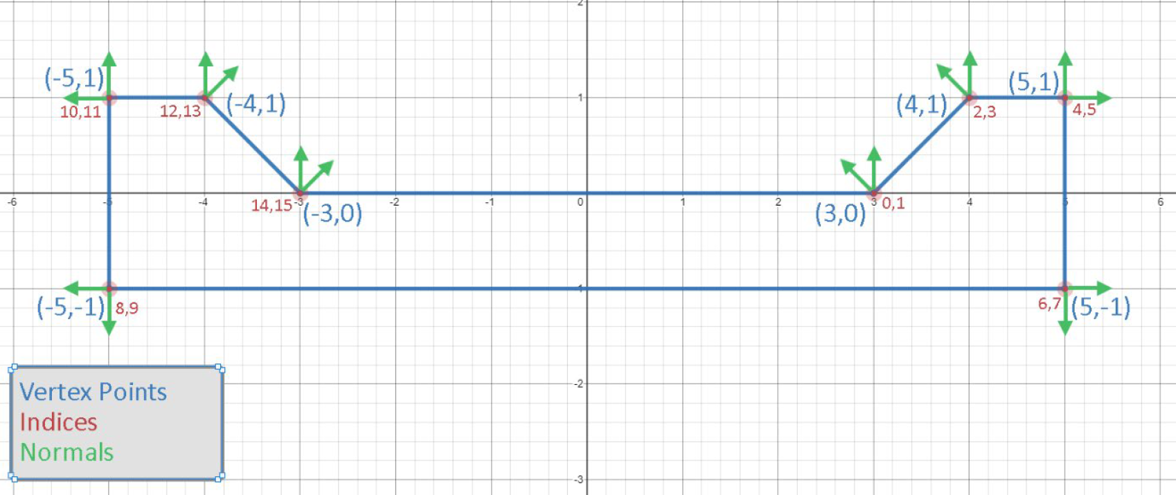
2D Cutout Mesh
When wanting to procedurally generate a mesh, all vertex data to create a 2D cutout of the shape of that mesh needs to be taken into consideration. As shown on the picture below, the outline of a road-like mesh with a curb is drawn out, marking each possible vertex with its according data (index, position and normal). For now this data is predefined, but for example could be retrieved from a chunk of an existing 3D mesh as an extension to my implementation.
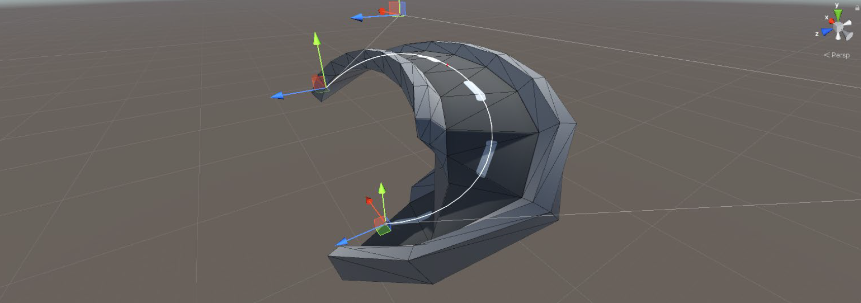
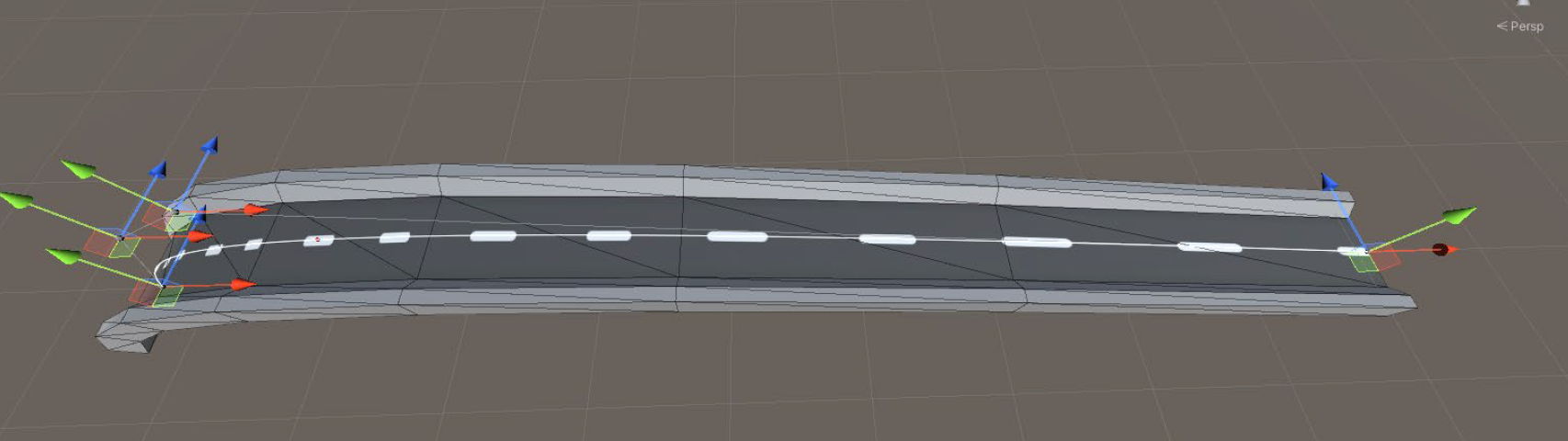
Forming Procedural 3D Mesh
The next step would be to start instantiating this 2D mesh shape multiple times along a defined spline, and orienting those meshes by the local transformation matrix of each respective point they are sitting on. It is then necessary to loop over all the vertices defined for every 2D mesh segment that was generated, connecting the currently evaluated vertices with the ones who share the same index of the next 2D mesh segment. Depending on how high the user wants the polycount of the final mesh to be, more iterations of 2D meshes can be instantiated and chosen to loop over. In this projects example, this will yield a visual 3D road mesh.
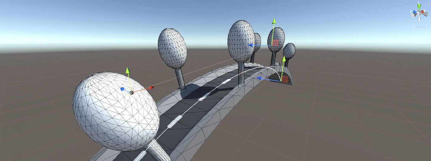
Procedural Placement of Existing Meshes
As a last, and simple, addition to the implementation I added the possibility to generate existing 3D meshes along the spline as well. Similar to the previous example, it requires dividing your spline into x-amount of segments and picking the points along the spline you want to instantiate an existing 3D mesh on. Again, it will be necessary to retrieve the local transformation matrix of that point to orient the instantiated mesh correctly.
Results & Limitations
Results
As displayed at the start of this page, when combining the mentioned features you get the following final results:
Limitations
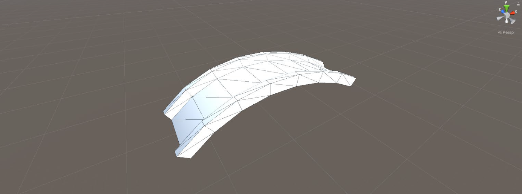
Though it was very cool to see these working results, there are limitations to my implementation which should not stay unmentioned. Visual artifacts in the mesh can arise when creating too sharp angles between control points to define the spline (see image below). When unevenly dividing the space between control points, this results in unevenly divided parts of the generated mesh as well. This causes UV stretching issue (see image below), but can be fixed. If you would like to know more about certain implementation details, other limitations and solutions for them, please do have a look at my full paper.
Credits & Contributions
All used materials/papers and other resources can be found at the end of the written paper about this research, starting at page 29.